From 90W PoE++ Input to 4-Port PoE Output Expansion
Understanding PoE power redistribution, 90W IEEE 802.3bt input architecture, and hardware topology for high-density edge deployments.
An IEEE 802.3bt PoE passthrough switch is a PoE-powered inline Ethernet expansion hub that receives up to 90W IEEE 802.3bt Type 4 PoE++ input (52V–57V DC) and redistributes available power and Gigabit data through four IEEE 802.3af/at PoE+ downstream ports without requiring local AC power infrastructure.
• Core Topology: Upstream 90W PoE++ input (Port 5) → Internal power management and DC/DC conversion stage → Four downstream PoE+ PSE outputs (Ports 1–4).
• Key Architecture Benefit: Extends Ethernet and PoE deployment beyond the standard 100-meter limitation by creating a 200-meter network path (100m uplink + 100m downlink) through an active powered edge node.
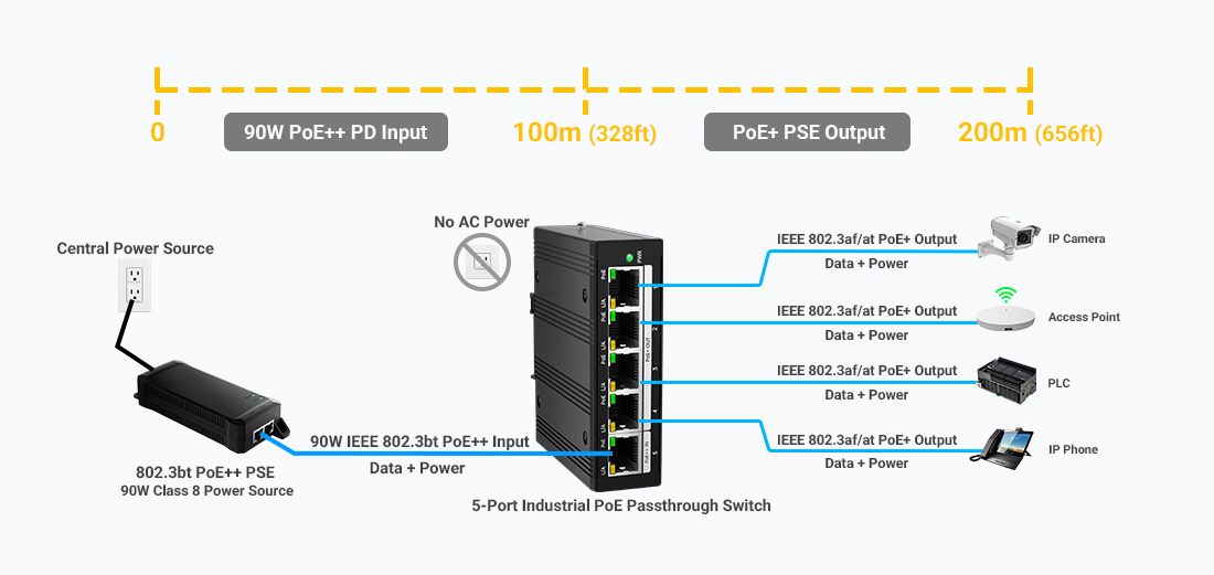
A 5-port industrial PoE passthrough switch uses a 90W IEEE 802.3bt PoE++ input to regenerate Ethernet data and distribute PoE+ power to four edge devices without requiring local AC power.
1. Hardware Mechanics: Step-by-Step Energy & Data Path
The PoE passthrough process relies on Layer 1 power detection, classification, and intelligent power management across four operational phases:
1
Upstream 4-Pair PoE++ Input Detection
The upstream PSE provides up to 90W IEEE 802.3bt Type 4 PoE++ power over all four twisted pairs. The passthrough switch performs PoE detection and classification before accepting incoming power.
2
Internal Power Management & System Operation
A portion of the incoming power budget is consumed by the switching controller, PHY components, and PoE management circuitry. The remaining available power is allocated for downstream PoE+ outputs.
3
Downstream PoE+ Power Allocation (Ports 1–4)
The four downstream ports operate as IEEE 802.3af/at PoE+ PSE outputs. They automatically classify connected devices such as IP cameras, wireless access points, and IoT terminals, providing up to 30W per port according to available power budget.
4
Gigabit Data Regeneration
The non-blocking switching fabric receives and retransmits Ethernet frames at 10/100/1000Mbps, creating a new Ethernet segment and extending deployment distance by an additional 100 meters.
2. Technical Comparison: Traditional AC-Powered Edge Nodes vs. 802.3bt PoE Passthrough Architecture
Conventional edge deployments often require dedicated 100V–240V AC power drops, local AC/DC power supplies, and additional outdoor electrical enclosures. In contrast, an 802.3bt passthrough node receives low-voltage DC power directly through the Ethernet cable.
| Technical Parameter |
Traditional AC-Powered Edge Node |
802.3bt PoE Passthrough Architecture |
| Operating Voltage |
100-240V AC local power input |
50-57V DC PoE++ input over Ethernet |
| Infrastructure Requirement |
AC wiring, breakers, local PSU enclosure |
Single Cat6/Cat6A Ethernet cable, no local AC outlet |
| Network Extension Capability |
100m standard Ethernet limit |
200m total path (100m uplink + 100m downlink) |
| Power Backup Strategy |
Distributed backup power at edge locations |
Centralized UPS protection at PoE source |
3. PoE Power Budget Calculation & Real-World Deployment Examples
Calculating power availability at the edge requires accounting for line resistance across 23AWG/24AWG twisted-pair copper conductors.
Power Budget Governing Equation
P_available = P_PSE_in - [ I² × R_cable ] - P_switch_system
• Upstream PoE++ Input (IEEE 802.3bt Type 4 / Class 8): 90.0W
• Estimated 100m Cat6 Cable Loss: ~9.2W (under full 4-pair load)
• Switch Internal Power Consumption: ~3.8W
• Estimated Available Downstream PoE Budget: ~77W
Example Downstream Load Combinations Based on an Estimated 77W Available Budget:
- Combination 1: 4× Standard Fixed IP Cameras (4× 7W = 28W Total) → Power Margin: 63.6%
- Combination 2: 2× Outdoor PTZ Cameras + 1× Wi-Fi 6 Access Point (2×25W + 18W = 68W Total) → Power Margin: 11.6%
- Combination 3: 1× Outdoor PTZ Camera + 3× Fixed IP Cameras (25W + 3×7W = 46W Total) → Power Margin: 40.3%
4. Industrial PoE Passthrough Switch Selection Checklist
When selecting an unmanaged, self-powered industrial Gigabit PoE Passthrough Switch for outdoor smart poles, transportation systems, or remote edge deployments, verify these critical hardware specifications:
Thermal Range
Fanless aluminum chassis designed for -40°C to +75°C operation helps maintain reliable performance inside sealed NEMA enclosures.
Surge Immunity
Integrated 6kV surge protection on RJ45 ports helps protect switching components against lightning-induced surges and transient voltage spikes.
Mechanical Form
Ultra-compact DIN-Rail mounting enables fast installation inside space-constrained control cabinets and outdoor enclosures.
Engineering Summary & Deployment Protocol
IEEE 802.3bt PoE passthrough switches eliminate the need for local AC power drops at remote edge nodes. By combining 90W PoE++ power input, automatic PoE power allocation, and Gigabit signal regeneration into a compact DIN-Rail footprint, system integrators can reduce installation complexity while extending network coverage.
Core Deployment Rule: Always ensure the upstream PSE provides true IEEE 802.3bt Type 4 (90W) power, deploy pure copper 23AWG Cat6 cable, and maintain a minimum 15% power safety margin for peak startup loads and temperature-related power variations.
Need Help Designing Your Industrial PoE Deployment?
Our industrial communication engineers specialize in PoE topology design, power budget analysis, and customized OEM/ODM switch solutions.

 Свяжитесь с нами по электронной почте
 Позвоните нам
 Адрес
Адрес



 Поддерживается сеть IPv6
 русский